EXPORT
TO ALL COUNTRIES!
Contact Us:
sales@licht-labs.com.


|
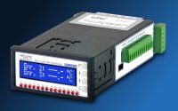
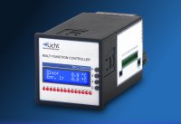
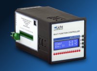
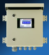
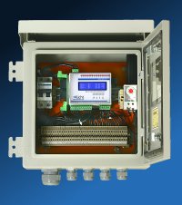
The MFC-300/T is a precise, highly reliable and versatile microcontrolled system for
power transformer temperature control. It is designed to read, infer, display and transmit
the top-oil temperature and that of up to 3 transformer coils. Its only direct measurement is the oil's, usually taken with RTDs (resistance temperature detectors). Coil temperatures are inferred upon evaluating the following parameters:
Documentation
Manuals
Software
Electrical, Structural and Environmental Characteristics
Technical Characteristics
Inputs
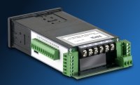
Oil (RTD), up to 3 windings (AC) and up to 5 additional RTD inputs. Compensated and linearized RTD inputs. AC inputs Isolated (≥ 1.5 kV, 60 Hz, 1 min.) with high linearity current transformers and converted to RMS values for improved noise immunity. Resolution 16 bits. Interface Options RS485, optically isolated (≥ 1.5 kV, 60 Hz, 1 min.), with MODBUS or DNP3 protocol support. USB for local configuration or Ethernet for IEC61850. Analog Outputs Software configurable current loop: 0-1, 0-5, 0-10, 0-20 or 4-20 mA. Isolated outputs (≥ 1.5 kV, 60 Hz, 1 min.). Relays 12 relays: 10 user configurable relays, 1 relay for RTD failure and 1 relay for power supply failure. A user configurable relay can be associated with any channel, and has an individual temperature setpoint, temperature hysteresis, current setpoint, current hysteresis, forced activation, activation logic and timeout. 4 relays support pairwise alternate activation. Switching capacity of at least 5A x 250 Vac or 0.5A x 125 Vdc. Galvanic isolation ≥ 1.5 kV (60 Hz, 1 min.). Display 2 lines, 16 characters each (5 mm). LCD with backlight. Events The highest temperature per channel per hour for the last 24 hours is stored in non volatile memory. Software Configurable Parameters
The MFC-300/T was developed to provide the user with the greatest possible flexiblity,
such that all supervision and configuration can be executed on-site or remotely through
the existing communication channels.
Of all the software configurable parameters, we highlight the following: Set Point (°C) [1-10] (0 to 255 °C) Temperature set point for relays 1-10. Hysteresis (°C) [1-10] (1 to 255 °C) Temperature hysteresis for the activation/deactivation of relays 1-10. Set Point (I%) [1-10] (0 to 150 %) Current set point for relays 1-10. Hysteresis (I%) [1-10] (1 to 255 %) Current hysteresis for the activation/deactivation of relays 1-10. Delay [1-10] (0.1 to 25.5 min.) Delay for the activation of relays 1-10. Associated Channel [1-10] (Oil, Wdg. 1-3, RTD 2-6) Channel associated with each relay. Associated Function [1-10] (Alarm, Cooling) Function associated with each relay. Forced Activation [1-10] (Normal, Activated) Selects if a relay responds to temperature variations (Normal) or if it is permanently activated (Activated). Activation Logic [1-10] (Normal, Inverted) Defines whether a relay's activation logic is Normal (relay closes when its set point is exceeded) or Inverted (relay opens when its set point is exceeded). Indication Type (Temperature, Current, Percentage) Type of values indicated on the MFC-300/T's front panel. ΔT[1-3] (0 to 99 °C) Copper/Oil temperature gradient for coils 1-3. Represents the temperature difference between each coil and the oil under nominal load. IN[1-3] (0 to 5.0 A) Nominal current considered by the device for inferring coil 1-3's temperature. Alternate Activation (Disabled, 7/8 only, 9/10 only, 7/8 and 9/10) Refers to the alternate activation of relays pairs 7/8 and 9/10, typically used to ensure equal wear of the associated cooling hardware. Time Constant (τ) (0.0, or from 3.0 to 20.0 minutes) Time constant for the coils' first-order thermal model. When set to 0.0, considers that the transformer has zero heat capacity. m (0.5 to 1.0) Exponent for the used cooling method. Daily Cooling (Start) (00:00 to 23:59, in increments of 1 minute) Time of day at which all cooling relays are forcefully activated. Daily Cooling (Duration) (1 to 999 minutes) Duration of the forced cooling cycle. Communication
All functions accessible through the keyboard are also available over MODBUS, DNP3 or IEC61850 protocols, enabling the user to remotely:
|